Project 3 - Fault-Tolerant Library
Fault-Tolerant Library
Checkpoint: 11:55pm Tue 4/14
Final Deadline: 11:55pm Tue 4/21
Introduction
You will be implementing a subset of a Python class for fault-tolerant quantum circuits based on the Steane error correction code. Specifically you will be implementing methods to:
- Correct arbitrary single qubit errors
- Generate fault-tolerant circuits for the X, Y, Z, H, S, T and CNOT gates
- Decode a measurement into a logical 0 or 1
This is not everything that is needed to fully design fault-tolerant circuits. To do so, we would also need to design fault-tolerant circuits for ancilla preparation, however we will assume that the Qiskit implementation of this can be done fault-tolerantly in order to narrow the scope of this project.
The circuits you build will have non-unitary operations (namely, measurement and classically-controlled gates), which prevents us from using the append method as in previous assignments, but you can use the compose method. This works in a similar way but doesn’t try to convert the second operand into a unitary operation.
Part I: Preparing the Steane State and Correcting Errors
In lecture, we showed how a logical |0⟩ can be represented across 7 qubits as an equal superposition of all even-weight Hamming codewords. For this project, the most significant bits of a statevector will be listed to the left, and so the parity bits are laid out as follows (starting at bit index 1):
| Bit index | 7 | 6 | 5 | 4 | 3 | 2 | 1 |
|---|---|---|---|---|---|---|---|
| Encoded bit | d₄ | d₃ | d₂ | p₄ | d₁ | p₂ | p₁ |
| Covered by parity bit? | 7 | 6 | 5 | 4 | 3 | 2 | 1 |
| p₁ | ✓ | ✓ | ✓ | ✓ | |||
| p₂ | ✓ | ✓ | ✓ | ✓ | |||
| p₄ | ✓ | ✓ | ✓ | ✓ |
The set of Hamming codewords with an even number of 1s is (again, with the most significant bits listed on the left):
|0000000⟩, |1010101⟩, |1100110⟩, |0110011⟩, |1111000⟩, |0101101⟩, |0011110⟩, |1001011⟩
A logical |1⟩ can be represented as an equal superposition of all odd-weight Hamming codewords, which we can get as the bitwise negation of the codewords above.
As discussed in lecture, we can correct an arbitrary X rotation on a single qubit by measuring the parity bits and performing conditional X gates as necessary (conditional gates not shown below):
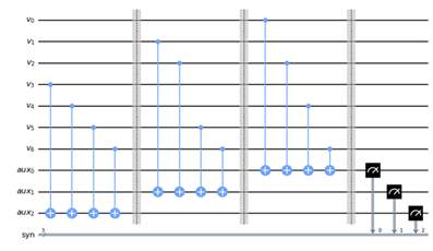
See labs 9 and 10 for guidance on how to conditionally apply gates based on a classical measurement.
Phase-flips can then be corrected by applying the same circuit, in which the code bits (listed as “v” above) are sandwiched between H gates. The sequence of these 2 circuits together will correct an arbitrary error on a single qubit.
Since quantum circuits require exponential resources to simulate, we are requiring that you limit the number of qubits used in your circuit. The public tests include checks to ensure you do not go over these limits (many of them can be implemented using fewer).
You should reset the ancilla bit to |0⟩ after each bit/phase-flip correction (you will need to use the reset instruction since uncomputation is not possible for non-unitary transformations involving measurement):
anc = AncillaRegister(1,"anc")
qc.reset(anc) # sets each ancilla bit to |0⟩
Your constructor for your circuit must initialize your circuit an encoding of the |0⟩ state. There are unitary circuits to do this, but the easiest way is to just apply error correction to the default |0000000⟩ state. This will “correct” it to the nearest valid Steane state, which happens to be |0⟩_steane. You can then apply other fault-tolerant gates to map it into any desired logical state.
In order for us to inject errors into your circuit to test your error correction, we need access to an underlying QuantumCircuit. The method get_phys_circ should return the underlying circuit (not a copy) that can be modified (this is the default behavior in Python when returning a member variable, so you shouldn’t need to do anything special). get_log_clbit and get_log_qbit should return the physical classical and quantum register objects, respectively, that represent the indicated logical qubit.
Part II: Fault-tolerant Error Correction
The error correction circuit described earlier works as long as no bit errors occur during the error correction circuit, which can be assumed when the parameter FT_EC is set to False when constructor the circuit. However, as described in lecture 22, an error on one of the auxiliary qubits can kick back to multiple data qubits, rendering error-correction useless.
When the parameter FT_EC passed to the quantum circuit constructor is set to True, you must instead construct a fault-tolerant version of error-correction which does not multiply a random qubit error when it occurs in the middle of the error correction circuit. As described in lecture 22, the below circuit measures a number of 1s which matches the parity of the number of 1s in data without disrupting the superposition, as long as the ancilla qubits are initialized to an equal superposition of even-weight bitstrings, and does so in a way that a single error does not propagate to multiple bits.
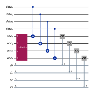
You may assume that the initialize method provided by Qiskit works fault-tolerantly, but since an error may cause the measurement to be incorrect, you must perform the above sequence twice (including re-initializing the ancilla qubits) and see if the measurement outcomes agree with each other. If not, keep repeating the process until they do agree.
Repeatedly applying a circuit a variable number of times can be done with the while_loop function. The syntax for this is
with qc.while_loop(expression):
    # quantum circuit operation here
where expression is an expr object. These are special objects that can be formed from boolean operations on classical registers and bits. You will most likely find the bit_xor, equal and not_equal methods most helpful in constructing these expressions. bit_xor can take two n-bit classical registers and perform bitwise XORs on each bit to yield an n-bit logical value, and equal and not_equal can take two classical registers, or a classical register and a literal value and evaluate to true/false based on their comparison. These methods also take in other expr objects as arguments so they can be built up recursively
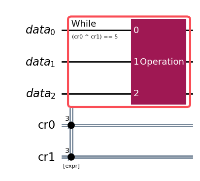
For example, the below code will keep applying some gate “Operation” while (cr0 ^ cr1) == b101:
from qiskit.circuit.classical import expr

data = QuantumRegister(3, name="data")
cr0 = ClassicalRegister(3,name="cr0")
cr1 = ClassicalRegister(3,name="cr1")
qc = QuantumCircuit(data, cr0, cr1)
# [measurements omitted]
expression = expr.equal(expr.bit_xor(cr0, cr1), 0b101)
with qc.while_loop(expression):
    qc.append(Operation, data)
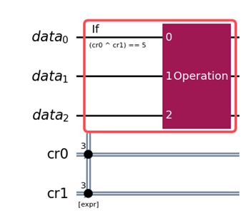
If you need to conditionally apply gates once based on an expression, you can use the if_test method. This applies the specified operations only once if the condition is true, otherwise proceeds in the program:
with qc.if_test(expression):
    qc.append(Operation, data)
We will test your fault-tolerant error correction circuit by randomly injecting single qubit errors anywhere in the circuit (besides state initialization) and checking that the error did not propagate, i.e. that it can still be corrected by applying another round of error correction with no error.
To provide more granular feedback, you must implement the helper function get_even_weight_state which takes an integer n and provides a list of complex values describing the statevector an equal superposition of all even-weight n-bit strings.
These Qiskit functionalities will be discussed more in lab 11.
Part III: Fault-tolerant Gates
As discussed in lecture 21, you will need to evaluate which gate operations must be applied transversally and which cannot.
These gates must be designed such that an error affecting one qubit before the gate is applied can be corrected by applying the error_correction circuit after the gate.
You will most likely find designing the encoded T Gate most challenging, since it cannot be implemented transversally. Below is the implementation of the T gate discussed in lecture.
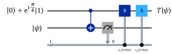
We designed it considering one qubit each for the code and ancilla qubit. You will need to extend each logical qubit into 7 physical qubits. You can use the initialize method to set the auxiliary qubits to the appropriate value, which you may assume works fault-tolerantly. This works by passing in a Python list representing the statevector of the corresponding qubits. For example:
anc = AncillaRegister(2,"anc")
qc.initialize([0,0,1,0],anc)
will set the two ancilla bits to the state |10⟩. The classically controlled X and S gates will need to be triggered only if the measurement across all physical qubits corresponds to a logical 1. You must also ensure measurement is done fault-tolerantly, which requires could use a parity check similar to the fault-tolerant error correction in section II, or could more simply directly read the result to a classical register and use expressions to apply the X and S gates. You may need to add an additional register using the add_register function.
You must also ensure that the final state is encoded on the original code qubits, unlike the ancilla bits shown in the circuit above.
To provide more granular feedback, you must implement the helper function get_magic_T_state which returns a list of complex values describing the state vector (|0⟩ + e^(i*pi/4)|1⟩.
Part IV: Decoding Measurements
At the end of your tests, you will need to perform measurements and decode the result. Since errors can generally occur during or immediately before measurement, you will need to perform error correction on the measured bit string. However, the measured result is a classical bitstring, so you will perform the error correction classically rather than with a quantum circuit. decode_measurement will take in a string representing the measured result of 7 qubit logical |0⟩ or |1⟩, perform error correction if needed, and return the int 0 or 1 as appropriate, along with True/False to indicate whether error correction was applied.
Part V: Restrictions
You may use anything in the Qiskit SDK and the numpy, math, random, and unittest packages.
Part VI: Testing
You must provide a set of test functions written in tests_p3.py to the autograder. You must use the Unittest model discussed in lab. Your tests will be graded on whether they cause assertion failures when run on buggy solutions, but do not cause assertion failures on correct implementations. We will test the error correction functionality of your circuits by randomly inserting single-qubit errors somewhere in your circuit and verifying that it is handled correctly.
Part VII: Submission and Grading
Submit p3.py and tests_p3.py to the autograder using the direct link at the top of this page.
There will be one checkpoint for this project, worth 10% of the overall project grade. It will be calculated using your score for all suites (including mutation testing) not involving the T gate, fault-tolerant error correction, or state preparation. The final submission is worth 90% of the overall project grade and will be graded on all tests. Late days may not be used for the checkpoint.
We will grade your code on functional correctness. As a reminder, you may not share any part of your solution with others. This includes both code and test cases. Doing so will result in an honor code violation. You will get feedback on your total score, but you will not have access to what the private test cases are checking for.
Efficiency is not graded, but your code must complete in a reasonable amount of time. Runtime tends to grow exponentially when you add qubits, so we will include checks to make sure you are not using signficantly more quantum bits than necessary.